I. Hardware Requirements
You will need a PC with blue tooth capability running Windows 7 (32 bit), preferably Windows 8, 8.1 or 10.
II. Software Installation
Down load BCU Editor and Data Analysis programs using the following link. To operate these codes you will need the licensing information that you received from CAS when you purchased your system.
www.CASupercharging.com/licensing
Note: A one year renewable license is included with the purchase of each CAS Boost Control Module. Optional 5 years licenses are available. If you have multiple units they can all be programmed and analyzed using a single PC/license. In this instance you will want to do a “license delete” when ordering a 2nd or 3rd BCU.
III. Establishing Communication
- Power up PC and Boost Control Unit.
- Open PC Control Panel, click “Add a device” and follow self prompting instructions.
- When communication has been successfully established the BCU(s) should appear in your PC’s Device Manager Window.
IV. Programming the BCU
The BCU Editor program is used for programming BCU functions, including parameters that effect performance and enabling/configuring the data logger. The editor also features real time digital displays of BCU functions.
EPR Calibrations
- Open the BCU Editor Program.
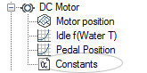
- Open the DC Motor Tab on the left tool bar.
- Open the Constants Tab.
- Modify DC Motor Constants as desired.
- Enter Apply, and then Close.
- Save new configuration to PC hard drive using “Save” or “Save As” command.
- Open “SYSCON” on the Toolbar.
- Open “Flash R1 ECU”.
- Follow self prompting commands.
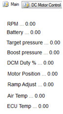
Real Time BCU Monitoring:
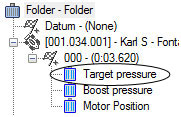
The digital table in the upper right corner of the Editor Window displays operational BCU characteristics as well as several programmed parameters. It is useful for verifying program changes as well as BCU functionality. For example, by electrically disconnecting the Safety Shut-off valve and triggering the system “on” you can observe EPR operation.
V. Data Logging
The BCU Editor program is used for configuring the BCU data logger and downloading data from the logger to a permanent file location.
Configuring the Logger:
- Open the Editor Program.
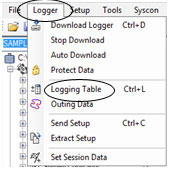
- Click on the Logger Icon.
- Click on the Logging Table Icon.
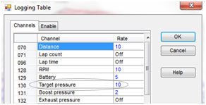
- Edit values in Logging table, turning on and setting sampling frequencies of the parameters to be monitored.
- Click ok.
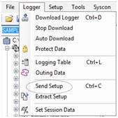
- Click “Send Setup” to download logging configuration into BCU.
- Follow self prompts.
 VI. Data Analysis
The BCU Analysis program is used for displaying time domain information for the variables that were configured to be tracked by the BCU’s data logger.
Data Viewing:
- Open the BCU data analysis program.
- Open “FILE” on the toolbar.
- Open “Add Outing” if the display is empty or “Replace Outing” if switching data sets.
- Select data file you wish to display.
- Right click on displayed variable(s) if you wish to add or change the parameters displayed.
- The graphical display can be printed, Y axis scaling altered, channel colors switched and X axis scaling altered (zoomed in or out to facilitate analysis. Also, multiple runs can be overlaid for comparative purposes).
I. Introduction to Tuning
The operation of a Compressed Air Supercharging system requires a number of mechanical and electro-mechanical components to work in concert. Examining a schematic of the system reveals that the over-arching principle is not terribly complex; however the proper tuning of a system requires a fair amount of finesse. To do so requires computer skills analogous to those needed for tuning an aftermarket EFI system and an understanding of the operational principle and operating protocol under which a CAS system operates.
This document is intended to provide an engine tuner who possesses the skills described above with the information necessary to tune a CAS system properly. For an individual who is not experienced in EFI engine tuning this process can be quite daunting and is not recommended; in that instance it is highly recommended that an experienced tuner be engaged for support.
Before delving into the actual tuning details of a CAS system it is important to understand the process which you will be controlling and the impact that changes to the programmable boost controller will have on system performance.
II. Understanding System Response
The operation of a CAS system can be broken down into two main phases: 1) Vehicle Launch or “MAPTarget attainment”; the period during which a system is activated and engine manifold pressure is rapidly increasing from atmospheric to programmed target levels and 2) Down Track Performance or “MAPTarget maintenance”; the period during which engine manifold pressure is at or near target levels.
Vehicle Launch: When a system is triggered “on” it takes approximately 200 ms for the Safety Shut-off valve to open and the intake manifold to be pressurized.
The EPR is capable of full shut to full open or vice versa in 90 ms. If the BCU MAP targeting algorithm is triggered at the same time the Safety Shut-off is commanded on, the EPR will be wide open before the Shut-off Valve and Ejector Isolation valve can react. The result will be a significant MAP overshoot followed by an oscillating over-boost, under boost “wobble” that may or may not recover during a run.
To compensate for the mechanical time constants of the system components, the BCU feedback algorithm must be altered or biased so that boost reaches the target value in the minimum time possible without significant overshoot. This is the characteristic that must first be tuned before making full passes and will be somewhat unique to each vehicle and the starting line launch protocol employed. The goal being to have MAPActual closely approximate MAPTarget before the PID algorithm is fully engaged (how to do this will be covered in the Trackside Tuning Section).
Down Track Performance: Once a vehicle is tuned to launch correctly the PID algorithm can be tuned to optimize down track MAP tracking (maintaining minimal error between MAPActual and MAPTarget ). How to do so will be covered in the Trackside Tuning Section.
III. Control Scheme Theory
The control scheme used to attain & maintain target MAP is what we refer to as a “soft coupled” closed loop system. It is called that because there is not a direct mechanical link between the measured variable (MAP) and the control variable (EPR position). By varying EPR position the BCU controls the rate of airflow into the engine intake tract which in turn controls MAP.
The BCU controls EPR position via a Proportional – Integral – Derivative (PID) algorithm that changes motor position based upon the equation:
Motor Position Command (t) = Stationary Position Command
+Pgain*(MAPTarget – MAPActual)
+ IGain ∫t0(MAPTarget – MAPActual) dt
+ Dgain*d(MAPTarget – MAPActual)/dt
Pgain = Proportional Gain. The farther Manifold Pressure or “MAP” is away from the target value the “harder” the algorithm pushes on the ECAP motor in an effort to reposition the EPR to minimize this error.
IGain = Integral Gain. As MAPActual approaches MAPTarget the influence of Proportional Gain diminishes linearly. The integral function then becomes the dominant influence, incrementally increasing “push” on the EPR motor based upon a user programmable time step.
Dgain = Derivative Gain. The Derivative Gain can be used to prevent overshoot. As MAPActual approaches MAPTarget the Derivative function acts to reduce the “push” on the EPR motor based upon the rate at which the MAP error is decreasing.
IV. BCU Settings and Parameter Ranges
Pgain – Typical values are between 60 and 80. CAS systems are preset at 70. As gain increases system response will increase but, excessive gain will result in an unstable system that is uncontrollable. A system that requires a proportional gain outside of this range indicates that some other tuning parameters or hardware settings are off.
IGain – Typical values are between 25 and 40. CAS systems are preset at 30. Once a vehicle has launched and target MAP has been attained or, closely approximated the Integral function becomes one of the two dominant tuning parameters.
Dgain – Typically not used. However, small values: < 10 may occasionally be beneficial.
Integral Timer – Typical values are 8 ms – 10 ms. CAS systems are preset at 9 ms. The integral timer is the time step that the Integral Gain is incremented across. The system is very sensitive to this value. Typically you want to run as small a time step as possible without encountering what is known as “Integral Windup”. Examples of this will be given in the Trackside Tuning Section. The difference between a smooth EPR control signal and a wild saw tooth pattern can occur due to a change in this value of only 1 ms (.001 s). The threshold at which this occurs is usually between 6 ms and 7 ms.
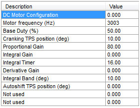
Motor Position – This is the angle that the butterfly in the EPR is held at when the system is armed but, inactive. It along with the Motor Delay variable play dominant roles in how well a car launches and if a stable MAP is attained. Appropriate values are a function engine size, launch rpm and target MAP. Calculating approximate values for motor positions will be discussed at length in the Track Tuning section. CAS systems are preset at 300. Launch quality and attaining MAPTarget is very sensitive to this variable.
Motor Delay – CAS systems are preset at 150 ms. In most all applications this variable will not be altered more than about – 20 ms to + 50 ms. It is the period of time after the system is triggered “on” that the EPR motor is held at the Motor Position location. These two variables correctly set allow the MAP pressure to approach target value prior to the boost control algorithm taking over and engaging the PRD gains. Another way to word it is that the system is “Open loop” for this period of time, switching to “Closed Loop” once it expires. Launch quality and attaining MAPTarget is very sensitive to this variable.
MAPTarget – This is the maximum MAP that is targeted. Units are inches of Mercury. If no MAP Ramp Rate is specified this value will be constant as long as the system is active.
MAPLaunch – This is the MAP that will be targeted immediately after the Motor Delay period ends. Target MAP will vary linearly from this value to MAPTarget over the period specified in MAP Ramp Rate. Units are inches of Mercury. If MAP Ramp Rate is set to -0- this variable is inactive.
MAP Ramp Rate – This is the period over which Target Map increases from MAPLaunch to MAPTarget. Units are ms. Maximum ramp period is 2.3 s.
Determining Initial Settings – The Basics
It is suggested that the factory settings for Pgain , IGain , Dgain , Integral Timer and Motor Delay be used as starting points for vehicle tuning unless you have direct carry over experience tuning a similar combination.
MAPTarget can be programmed to any target value desired, that is within the flow range capability of the CAS unit being operated on the vehicle; up to 60-in Hg, provided that the CAS unit being used has been sized correctly for the application.
Determining Initial Settings – The Advanced
Determining correct settings for the following variables to attain acceptable launch performance is where finesse becomes very important
Note: MAPLaunch, MAP Ramp Rate, and Motor Position are the variables that will make or break Launch Performance and strongly impact Down Track Performance.
As discussed in System Response there are mechanical and pneumatic time constants (response times) that strongly influence the rate at which the intake is pressurized once the system has been triggered. In addition the reaction of the engine/vehicle to the sudden and large increase in torque due to increased MAP interacts with the CAS system. As a result there are no generic settings for these variables that will work correctly on all vehicles.
An initial “best guess” of desired MAPLaunch and MAP Ramp Rate (if desired) will need to be made by the tuner.
Note: The last pre-run variable that needs to be determined by the Tuner is Motor Position. It is also the most difficult to predict and the most important.
If Motor Position is set at too large an angle, intake pressure will exceed the target value during the Motor Delay period. Too small a value and the control algorithm will over-boost the engine once the PID takes over.
Dynamometer Testing
Dynamometer testing is typically performed under either steady state/constant rpm conditions or using a fairly slow transient cycle. Calculation of Motor Position for these applications is straight forward two-step process:
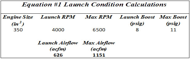
- Use equation #1 to verify that maximum target boost and maximum target airflow are within the working range of the hardware set you are running; Maximum airflow must be less than or equal to the cfm rating of your system. Note the Launch Airflow target.
- Use the chart contained in Figure 1 to determine estimated Motor Position associated with your Launch Airflow Target.
You now have all the initial settings necessary to perform dynamometer testing.
Track Testing
Vehicle launch is a highly transient operating condition with engine speed and air consumption changing extremely rapidly within the matter of 1 to 1-1/2 seconds in many applications. To launch properly Motor Position must be correctly set. To do so requires a thorough understanding of launch dynamics.
- Automatic transmission cars w/o transbrake and transbrake equipped cars that do not engage the CAS system prior to launch. In this instance the converter will be stalled at an RPM that is limited by either the rear brakes or torque limited by the engine.When the foot brake or transbrake is released and the CAS system is engaged at WOT engine speed and airflow requirement will begin to climb. At the same time MAP is increasing as the intake tract starts to filled/pressurized by the CAS system.By the time the Motor Delay period is over (150 – 200 ms after launch) the engine airflow requirement will be significantly above what was required with the engine stalled against the converter and MAP will be somewhere between atmospheric and MAPLaunch (or MAPTarget if no ramp rate is used).Approximately 400 ms after launch (actual time varies with converter, car weight &, torque increase due to CAS system) a correctly setup system will have attained programmed MAP levels and the torque converter will have locked up. An example of this is shown in Figure 2.
Note: The airflow requirement at the RPM and MAP that occur at the point where converter lock-up occurs is the value that is the value that should be used for calculating Motor Position. Figure 2
Note: It is suggested that you consult your torque converter manufacturer with vehicle specifics (weight, gearing & torque under boost) in order to make a reasonable estimate/initial guess of what Motor Position should be according to Equation #1.
- Automatic transmission cars w/transbrake that engage the CAS system pre-launch. Vehicles’ pre-launch engine rpm will be usually governed either by engine torque/converter stall or by ignition rev limiter.In these applications the system will usually be triggered just before launch. Starting line techniques can vary but, triggering the system at the time the last staging bulb is lit should provide an adequate amount of time prior to vehicle launch for MAP to be stabilized at desired launch level.This situation is much less transient in nature than that encountered in foot braked applications. As a result the ability to estimate Motor Position is less difficult. Use vehicle weight, gearing and estimated torque under boost to determine converter stall speed. From this use Equation #1 and Figure #2 to estimate requisite airflow and Motor Position.
- Manual transmission equipped cars. At this date no development work has been conducted on manual transmission equipped vehicles. The same basic principle outlined for foot braked automatic transmission cars applies. However, the rate of clutch “take up” and time to clutch lock-up has not been documented. Hence the time constants associated with rpm at time of clutch take up and time to clutch take up are not known and will need to be experimentally derived.
V. Trackside Testing
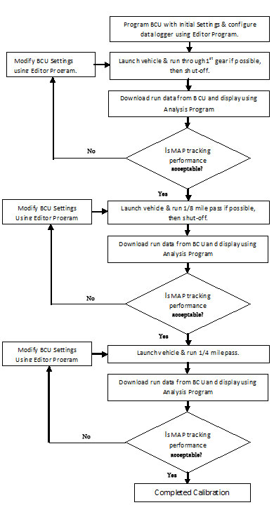
When track testing a vehicle for the first time it is important to work progressively. This process is presented in two forms for clarity: Step by Step instructions and an accompanying flow chart in Figure 3 detailing the process.
Vehicle Launch
- Launch the car, running out about 2 – 3 seconds or one gear change whichever comes first, then shutting off the system.
- Use the BCU Analysis program to evaluate the Run’s data. Modifications to BCU parameters should focus on getting MAP to target level by the time converter lock-up occurs, with a minimum amount of overshoot or undershoot. The primary tuning variable for this should be Motor Position.
- Repeat Steps 1 and 2 until satisfactory results are attained.
Down Track Performance
Once a vehicle is tuned so that MAPTarget is attained at the time of converter lockup, focus can be shifted to down track performance. This is the period of time where typically the Integral term (IGain) of the PID becomes dominant. Changes in engine rpm and thus airflow are limited to gear change rpm drops which in most cases do not change airflow requirements drastically enough to cause the Proportional term (PGain) to heavily influence MAP tracking performance.
- Launch the car and run through the first two gears or out to the 1/8thmile whichever comes first, then shut off the system.
- Use the BCU Analysis program to evaluate the Run’s data. Modifications to BCU parameters should focus on getting MAP to maintain target level for the duration of the run. The primary tuning variables for this should be IGain and ITimer.
- Repeat Steps 1 and 2 until satisfactory results are attained.
Track Testing Progression
I. Fault Tree Analysis
Failure analysis is broken down hierarchically. First a system level analysis is performed to determine if an issue lies with the setup/programming of a system. If a fault is not cured at that level then fault trees are designed to provide information as to which components may be contributing to the observed failure.
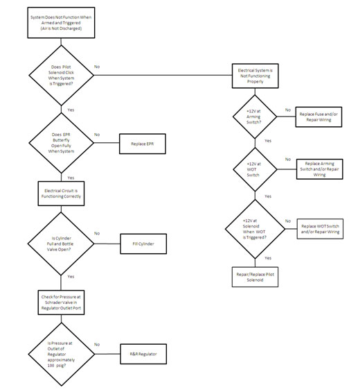
II. System Does Not Function
If a system does not function at all, the following fault tree is intended to help pinpoint the root of the failure.
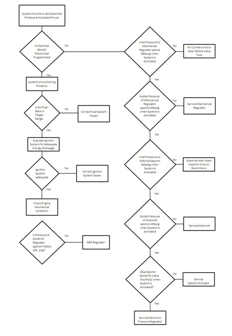
III. System Functions but not Correctly
If a operates but is not producing normal power, the following fault tree is intended to help isolate the source of the failure.