I. Is Compressed Air Supercharging the right Power Adder for My Application
It is important to understand that Compressed Air Supercharging has been created for drag racing applications only. CAS systems are not intended for usage on street vehicles.
The components in the Air Storage Module operate at a maximum pressure of 3300 psig, the standard pressure at which scuba equipment operates. When properly installed and cared for the hose(s) and components in this module are engineered to provide safe and robust service lives.
Warning: Improper installation and/or damaged components can lead to catastrophic failure, resulting in injury or death. It is imperative that CAS installation instructions are closely adhered to and that damaged components are replaced immediately.
II. Tuning Requirements
CAS Boost Controllers (BCU) are partially programmed at the factory with generic settings for some key parameters (see System Tuning document for details). Vehicle specific settings will need to be programmed by a tuner prior to operation. Subsequently data will need to be downloaded from the BCU after each pass, analyzed and programming changes made in order to attain optimized performance. This is an iterative process. A sharp tuner or one with experience on similar vehicle combinations can usually arrive at an acceptable combination within about 5 – 10 partial passes. An individual with no experience and light on intuition can easily get confused. This is why we highly recommend working with an authorized CAS Dealer/Tuner.
Minimal Skill Requirements: For an individual who desires to become proficient in tuning a CAS system the following are suggested as prerequisites:
1) PC proficiency including loading software and dealing with general MS Windows related issues or, close proximity to someone who is.
2) Experience programming aftermarket fuel injection system such as those offered by Edelbrock, EFI Technologies or similar.
3) Experience with data loggers and light data analysis techniques; properly tuning a system requires being able to look at time domain traces of manifold pressure actual, manifold pressure desired & motor position and determine changes in Boost Controller commands necessary to improve performance.
I. Safe Storage and Transport
For long-term storage, cylinders should be pressurized to no more than several hundred psig, have the Valve outlet capped and stored upright in a cool, dry location. During transport cylinders should be safely secured and protected from extreme temperatures.
CGA (Compressed Gas Association) standards require that aluminum cylinders exposed to temperatures over 3500 F be condemned.
II. Periodic Visual Inspection
Regularly inspect cylinders and valves for physical damage such as cuts, gouges or dents, signs of heat damage and general abuse. An annual inspection should be performed during which the Valve is removed and the Cylinder and Valve checked for internal contaminants and thread integrity (no signs of cracking or deterioration). Cylinders that show evidence of physical damage should be hydrostatically tested prior to refilling. Valves that show evidence of damage should be discarded.
Valves that are contaminated or exhibit abnormal operating performance characteristics should be disassembled, cleaned and rebuilt using CAS service package components.
III. Threads and Fittings
Be sure fittings and connection threads meet properly – never force. All fittings and hoses must be in good working condition and free of debris and oil. Never use thread sealant (Teflon paste, Teflon tape, etc,) on any CAS fittings except for the small pipe thread fittings used in pressure compensation and actuator lines.
Do not attempt to use fittings anywhere in the system other than those supplied by CAS. The high pressure fittings used are designed to meet the working pressure requirements of the system. The medium pressure lines are designed to not only meet the working pressure requirements of the system but also yield the minimum pressure drop possible, to maximize system performance.
IV. Hydrostatic Testing
According to Department of Transportation regulations, all compressed gas cylinders pressurized to more than 900 psi must be hydrostatically tested every five years to verify their structural integrity. These tests typically involve filling the cylinder with water, placing it in a water-filled pressure chamber, and measuring the expansion of the cylinder as pressure is applied. Hydrostatic test pressures vary depending on the cylinder material, but they typically are performed at 1.5 to 1.66 times the cylinders service pressure. If the permanent expansion of a cylinder is 10 percent or more, the cylinder is condemned and removed from service.
Any time a cylinder sustains physical damage or is exposed to high temperatures, the integrity of the cylinder is suspect, and a hydrostatic testing is warranted. When a cylinder passes a hydrostatic test, new markings are stamped into the crown of the cylinder to indicate the test date.
V. Emptying Contents
High pressure (upstream of the Mechanical Regulator) lines and fittings should never be loosened or removed while the system is pressurized. Always shut the Cylinder’s Valve and completely vent the systems pressure using the Schrader valve in the Mechanical Regulators outlet fitting prior to disconnecting high pressure hoses or fittings.
VI. Cylinder Filling
Regardless of the type and size of cylinder, it’s important to get a good (and safe) air fill. The first thing to make certain of is that the technician filling your cylinder knows the correct cylinder pressure. We have firsthand experience with a scuba shop employee filling three 3290 psig type III composite cylinders to 4300+ psig, not realizing what had happened until all three cylinder’s PRD’s vented while they were sitting in the back of a vehicle when exposed to ambient temperature of 1200 F.
The service pressure rating for cylinders assumes a temperature of 700 F. The ideal gas law dictates that the pressure in the cylinder will rise or fall about 1% for every 100 F change in temperature of the cylinder’s contents.
Make certain your cylinder is being filled with standard breathable air, not high oxygen content blends such as Nytrox. Elevated oxygen contents lead to greatly increased flame temperatures and massive engine damage.
Air quality is a potential concern. Only fill cylinders using air from a trusted supply source. Before connecting the fill line, the connector should be either blown or wiped dry.
A maximum fill rate of 300-600 psi per minute is typically recommended to prevent excessive heating during the fill, regardless of whether the cylinder is filled while in a H2O immersion tank or merely in ambient air.
VII. Cylinder Markings/Coding
CAS cylinders are marked with stamped coding in the neck area:
- The first group of letters “TC-3ALM 234” is a designation denoting the cylinder is in aluminum and is in compliance with Canadian transport regulations.
- The second group of letters (DOT3AL-3400) denotes that the cylinders are manufactured in the US; DOT stands for US Department of Transportation, 3AL denotes aluminum and 3400 is the maximum service pressure (3400 psig).
- The third grouping of letters, which is typically on the same line as the second group lists the cylinder’s serial number, manufacturer and manufacturing date. The manufacturing date is listed by month & year, for example: “01A07” was manufactured in January 2007.
Cylinders must be hydrostatically tested every five years to ensure that they are structurally sound. Each time a cylinder is hydrostatically tested, a new month and year is added to the markings, separated by a unique symbol designating the independent inspection agency (IIA) performing the test.
I. Theory of Operation
When a fully charged CAS system is triggered “on”, 3300 psig air is immediately throttled down to approximately 100 psig in the Mechanical Pressure Regulator. Accompanying this reduction in pressure is a huge reduction in temperature; Regulator outlet temperatures of -1500 F are not uncommon.
During operation as the storage cylinders are evacuated the pressure in them decreases resulting in a very rapid, near adiabatic expansion of the remaining air. Accompanying this expansion is a corresponding drop in the temperature of the air remaining in the cylinder. The reduced throttling effect that occurs in the Mechanical Regulator due to decreased pressure differential (outlet pressure remains constant as inlet pressure is reduced) is offset by the reduction in the temperature of the air entering the Mechanical Regulator.
The very low temperature medium pressure air stream is then throttle one more time in the Electronic Pressure Regulator before being discharged into the engine air intake tract. The throttling effect that occurs here is small compared to that which occurs at the Mechanical Pressure regulator but, similar in nature.
The end result of these expansion processes is that the charge air temperature entering an engine is dramatically lower than can be achieved with conventional MAP increasing technologies (supercharging and/or turbocharging with after-cooling). Hence very high charge densities can be attained at relatively low MAP levels.
II. Hardware Functionality
The following is a step by step explanation of what occurs when a CAS system transitions from an “off” to an “on” mode.
Step 1 – Opening Gate Valve on Cylinder: The first 1-1/2 to 2 turns CCW of the Handle on a CAS Gate Valve (GV-625) opens a pilot hole within the valve that allows a reduced amount of airflow to exit the valve and pressure downstream components all the way to the Safety Shut-off Valve (SOL-1440). This results in the pressure in the Cylinder equalizing with that between the Valve and the Mechanical Regulator (REG-625) at approximately 3200 – 3300 psig and the pressure between the Mechanical Regulator and the Safety Shut-off to Stabilize at approximately 100 psig (actual value varies with system configuration). This “filling” process is accomplished in a matter of several seconds if the primary is fully open.
Once the line feeding the Mechanical Regulator is fully pressurized the Gate Valve Handle can be turned an additional 5 – 6 turns CCW to fully open the main exit passage in the Valve.
Step 2 – Arming the System: With the system fully pressurized and the Gate Valve(s) fully open the system can be armed with the main power switch. Doing so energizes the Boost Control Unit (BCU-030) which in turn drives the EPR to the Motor Position that has been programmed into the BCU.
Step 3 – Triggering the System: With the system charged and armed triggering the BCU with an “on” command causes the Safety Shut-off Valve to open, air to pass through the EPR and the Isolation Valve in the Ejector to shut, resulting in the engine running solely on air being supplied by the CAS system. The EPR motor position will remain stationary with air flowing for the period of time programmed into the Motor Delay function.
Step 4 – Boost Tracking : Once the Motor Delay period has been exceeded the BCU drives the EPR motor open or shut in an attempt to attain and maintain the MAP target that has been programmed into the BCU. Adjustments are continually made 100 times per second until the “on” command is released.
Step5 – Return to Quiescent : Once the “on” command has been terminated the Safety Shut-off is closed, the Ejector Isolation Valve is opened, returning the engine to normally aspirated operation and the EPR returns to the Motor Position location that is programmed in the BCU.
Step 6 – Run Termination: When not in use the Gate Valve handle should be turned fully CW to isolate the cylinder contents from downstream components. If the system is not to be used for an extended period it is recommended that the air trapped between the outlet of the Gate Valve and the Safety Shut-off be vented using the Schrader Valve that is located in the Mechanical Regulator outlet fitting.
III. Operational Requirements
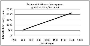
Step1 – Determining Required Flow Capability: System sizing and equipment selection requires first determining airflow requirements based upon horsepower targets. The chart below provides a reasonable estimation of airflow requirement as a function of horsepower.
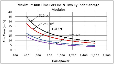
Step2 – Determining Storage Capacity Requirements : The accompanying chart below displays run time as a function of horsepower (based upon the calculations performed in Step 1). In all instances it is recommended that on-vehicle storage capacity be at least 25% greater than what is expected to be consumed during operation.
IV. System Installation
Installation of a compressed air supercharging system involves the careful layout and integration of three main groups of components or “Modules” into a vehicle; Air Storage, Air Metering and Boost Control. Detailed instructions for the installation of each of these modules are available from CAS.
V. System Tuning
Boost Control Modules are pre-programmed with baseline settings that are typically common to most applications. Additional program and track tuning will be required to correctly tune a system for each application. A detailed tuning instruction document is available from CAS.
VI. System Troubleshooting
Most system level performance issues are traceable to calibration errors or, incorrect component/system selection for a specific application. If however, a system has worked well previously and is suddenly exhibiting performance issues or a component is obviously not operating correctly, service may be in order. A detailed troubleshooting document is available from CAS.
VII. Component Servicing
Most CAS components are field serviceable; however, some require specialized tools that are not commonly available. Disassembly, inspection and reassembly instructions, as well as Assembly drawings detailing replaceable subcomponents are available from CAS for all major components.
I. Filling the Cylinder for the First Time
High Pressure Cylinders are shipped empty. Included with each Air Storage Module is an adaptor fitting that will allow the tank to be safely filled to 3300 psig at any facility that is equipped to fill standard scuba tanks.
Alternatively, Cylinders can be filled remotely provided standard safety procedures for filling high pressure cylinders are adhered to.
Compressed Air Supercharging tanks are available in two sizes: 125 scf capacity (aluminunm cylinders) and 158 scf (composite wrapped aluminum cylinders). Ratioing your tanks volume to a standard scuba tank (80 scf) and multiplying this times what your local dive shop charges for a normal scuba fill is a good general guideline for what a fill should cost.
II. Electrical System Checkout
With the system completely depressurized/empty the operation of the system including data recording and analysis functions should be checked. To do so:
- If the system has been pressurized, close the Cylinder Valve and blled all air from the system using the Schrader Valve located in the Mechanical Regulator’s outlet fitting.
- Turn arming switch to “on” position.
- Activate system by moving throttle to WOT. In Double Redundant Systems the Transbrake/Clutch switch should be in their fault positions (normally closed).
- When WOT is reached two things should occur: 1) There should be an audible “click” emanating from the Lock-off valve due to pilot operation and 2) The EPR butterfly valve should be driven fully open and the EPR should emit a high frequency “hum”.
- Toggle the engine to WOT and back to idle several times to verify proper electrical system operation.
- Return arming switch to off position
- Down load data logger using BCU Editor program..
- Review system performance using BCU Analysis program. EPR should open fully within 100 ms after Motor Delay period has expired.
III. Hose Seal Integrity (External Leaks)
- Slowly open Cylinder Valve 1 to 1-1/2 turns. This will open the pilot seat. As the pilot begins to open you will hear an audible “rush” as the system becomnes pressurized. After approximately 3 seconds, shut the valve.
- Examine all hoses and fittings for leakage.
3a. If leakage in high pressure AN fittings (hose ends) is noted, check fitting torque; 70 ft-lb maximum.
3b. If leakage in medimum pressure hose connections is noted, retorque fittings; 35 ft-lb maximum.
Note: If the fittings still leak after retorquing, chances are that the copper AN seals were not properly seated when installed or were damaged. De-pressurize the system using Schrader valve located in Regulator outlet port. Reset/replace Seals as necessary.
IV. Basic Operational Tips
Pressurizing the System
The Compressed Air Supercharging Bottle Valve used in your system is a unique two stage design. The first 1-1/2 turns open a .060-in orifice pilot valve that allows the inlet of the Mechanical Regulator to equalize with the the contents of the High Pressure Cylinder. Once equalized the Bottle Hand Wheel can easily be opened an additonal 5 to 5-1/2 turns to maximize flow area and minimize pressure drop. When operating note the following operational characteristics.
- Turn the Bottle Valve Handle 1-1/2 turns CCW.
- Wait three seconds. During this period the Mechanical Regulator may make a small “thunk” noise as the internal piston shuts once downstream pressure has reached 100 – 120 psig.
- Turn Bottle hand wheel additional 5 to 5-1/2 turns until wheel stops.
- The system should now be ready for operation, once the arming switch is toggled “on”.
Note: In systems with two Cylinders once the first Cylinder’s Valve has been opened and downstream pressure is equalized, the 2nd cylinder should open easily and there wll be no “obvious” Pilot Valve movement as pressure is already equalized on both sides of the valve. . This does not impact the total number of turns required to open the valve fully.
De-Pressurizing the System
- Shut the bottle valve by turning it full clockwise until wheel stops. You will find it handy to count revolutions as you shut the valve; It is possible to confuse shutting the valve fully with merely coming up against the engagement of the pilot valve shuttle.
- Remove the cap from the Schrader valve located on the outlet port of the Mechanical Regulator
- Bleed system pressure by pressing axial on the core of the Schrader Valve.
- Replace cap when system is empty.
System Cleanliness
Whenever the Compressed Air Supercharging System is not in usage, shut the Bottle Valve fully. The Mechanical Regulator features a special conical chlorofluorocarbon internal seal and hardened burnished seat that is verified to be “Bubble Tight” before leaving the factory.
Contaminants can significantly degrade this seal, resulting in a slow internal leak. If this occurs outlet pressure will eventually reache 140 – 145 psig whereby the downstream PRD will vent to prevent overpressurization. If this phenomena happens, the contents will be emptied over a period of time.
Cylinder Valve Operation
Do not overtorque Bottle Valve Handle when opening or closing. Merely turning the handle up to its stop is adequate to ensure that it is fully open or fully closed. In extreme cases overtorquing the handle open can result in a stuck pilot valve, requiring disassembly of the valve to free the mechanism.
Cylinder Pressure Monitoring
Usage of a gauge or pressure transducer to monitor the high pressure side of a system is paramount in obtaining proper performance. CAS recommends and uses exclusively Autometer P/N 4396 in conjunction with the remote high pressure sensor and power source available from CAS under P/N SENS-4000.
The medium pressure side of the system (Mechanical Regulator to EPR) is not usually monitored. However, monitoring pressure at the outlet of the Safety is a great way to get immediate feedback as to how your system is operating and can be valuable should any troubleshooting every be required.
I. Determining Storage Capacity Requirements
The first step in creating a proper Air Storage Module is to determine the storage capacity required for your application. The Table below provides a reasonable estimation of air consumption rate and storage capacity requirements.
| HP | Estimated Airflow * (cfm) |
Volume Consumed (scf) ** | |||
| 6 sec | 8 sec | 10 sec | 12 sec | ||
| 100 | 143 | 14 | 19 | 24 | 29 |
| 200 | 286 | 29 | 38 | 48 | 57 |
| 300 | 429 | 43 | 57 | 71 | 86 |
| 400 | 571 | 57 | 76 | 95 | 114 |
| 500 | 714 | 71 | 95 | 119 | 143 |
| 600 | 857 | 86 | 114 | 143 | 171 |
| 700 | 1000 | 100 | 133 | 167 | 200 |
| 800 | 1143 | 114 | 152 | 190 | 229 |
| 900 | 1286 | 129 | 171 | 214 | 257 |
| 1000 | 1429 | 143 | 190 | 238 | 286 |
Table 1
* Based upon BSFC of .5lb/hp-hr and 12:1 air/fuel ratio.
** When constructing an Air Storage Module, minimum storage capacity should be at least 10% greater than calculated usage. scf = “Standard Cubic Feet”
II. Choosing Number, Size and Type of High Pressure Cylinders
Using the volume of air you expect to consume during a run as estimated in Table 1, determine the number and type of cylinders best suited for your application. CAS High Pressure Cylinders are currently available in two sizes and types of construction.
- 125 scf Aluminum.
- Weighs approximately #45 and #54 full.
- 75” diameter X 35” tall.
- 158 scf Aluminum Inner, Carbon Fiber overwrap
- Weighs approximately #22 empty and #33 full.
- 0” diameter X 35” tall.
| Storage Capacity | Material | Cylinder P/N |
| 125 scf | Aluminum | CYL-125AL |
| 158 scf | Carbon Fiber/Aluminum | CYL-158CF |
III. Cylinder Mounting Options
Aluminum clamshell brackets are available from CAS for applications where generic mounting can be accommodated. In many instances it is preferable to have custom bracket mounts fabricated as part of your vehicle’s roll cage or frame structure.
| Cylinder Size | Bracket P/N |
| 125 scf Aluminum | BRKT-775 |
| 158 scf Carbon Fiber | BRKT-800 |
IV. Mechanical (High Pressure) Regulator
Currently we offer three variants of our high pressure regulator. The units are identical except for outlet pressure setting, which is not user adjustable. For optimum system performance you should select a regulator that is set for the desired output of your engine.
| Max HP | Outlet Pressure Setting * | Dome Loaded | Regulator P/N |
| 500 | 80 psig | N | REG-625-001 |
| 700 | 120 psig | N | REG-625-002 |
| +850 | 120 psig ** | Y | REG-625-003 |
* Rated pressure setting is at low flow conditions.
** Refer to Tech Section for explanation of Dome Loading
V. High Pressure Hoses & Fittings
Hoses: Prior to purchasing any hose you must know the exact length of the hose(s) you need. To do so you first need to determine the mounting locations of your Cylinder(s) & Mechanical High Pressure Regulator. Keep in mind that you will be regularly installing and removing Cylinders to fill them, hence easy ingress, egress and connection of hose to the cylinders should be a primary consideration when laying things out.
It is strongly suggested that you purchase and install the Cylinder(s) and Mechanical Pressure regulator prior to measuring for and ordering High Pressure Hose.
The only high pressure hose that is approved for usage by CAS is Kongsberg T1700/2000-10. This hose is rated for 5000 psig working pressure at -750 F. It is the only hose that we are aware of that is compatible with the high pressures and low temperatures encountered with a CAS System.
Kongsberg lists the minimum allowable bend radius for T1700/2000-10 hose at 3.3-in., however, it is very stiff; Tight bends near where the hose connects to cylinders can make it very challenging to perform quick Cylinder changes. CAS recommends that you try to keep minimum bend radii no smaller than 5-in.
When determining hose lengths it is important to note that CAS hose lengths are measured fitting tip to fitting tip as depicted below. Mocking up hose length and routing using heater hose or a similar stiff substitute works well for accurately estimating lengths.
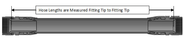
Note: Small errors in hose length measurement can make it very difficult to make the Cylinder to Hose connection when changing Cylinders.
Fittings: Currently Kongsberg only offers the T1700/2000-10 hose with AN style hose ends. In gaseous applications this type of hose end requires the use of conical copper washers to attain an acceptable seal.
In applications where two Cylinders are used a CAS WYE fitting must be used to transition from two hoses to one.
I. Safety Shut-off Valve
Every CAS system must be equipped with a Safety Shut-off Valve downstream of the High Pressure Mechanical Regulator. For optimum performance this valve should be mounted in the engine compartment as close to the Electronic Pressure Regulator as possible.
The Safety Shut-off Valve is the only component in the system that prevents the Storage Cylinder from bleeding down or emptying once the Gate Valve on the Cylinder is opened. Never attempt to run a CAS System without one.
Currently one size valve is available and supports applications up to 1200 cfm when matched with the correct Mechanical Pressure Regulator.
| Configuration | Shut-off P/N |
| Two Stage, Piloted with External Venting | SOL-1440 |
II. Electronic Pressure Regulator
The Electronic Pressure Regulator or “EPR” used in CAS Systems is an electronically actuated butterfly valve, based upon a highly modified BOSCH Drive by Wire design. For optimum performance this valve should be mounted in the engine compartment as close to the Ejector as possible.
Currently one size EPR is available and supports applications up to 1200 cfm when matched with the correct Mechanical Pressure Regulator.
| Configuration | EPR P/N |
| Electronically Actuated Butterfly Valve with Position Feedback | EPR-1260 |
III. Ejector
The Ejector used in CAS systems is of a single stage axial flow design with an integral pneumatically actuated isolation valve.
Currently one size Ejector is available and supports applications up to 1200 cfm when matched with the correct Mechanical Pressure Regulator. Intake tract hose connections are 3.50-in for both the inlet and outlet
| Configuration | EPR P/N |
| Ejector with Pneumatically Actuated Isolation Valve | EJ-3500 |
IV. Medium Pressure Hoses
Medium pressure hose used in CAS applications is AN size -20. It is sold by the foot and uses three piece hose ends that are user installed (available in either straight or 900 configurations).
When routing hose (from the Mechanical Pressure Regulator forward to the Safety Shut-off, between the Shut-off and the EPR or EPR to the Ejector) care should be taken to make the hose routing as short and straight as possible. Excess hose length, tight bends or kinking will increase pressure losses in the system and decrease system performance; significantly in higher output applications.
| Configuration | Hose P/N |
| AN -20 Hose | HSE-20-XX* |
| Straight Hose End | FIT-20-ST |
| 900 Hose End | FIT-20-90 |
| Fml-Fml Coupler | FIT-20-20 |
V. Ancillary Hoses
Ejector Isolation Valve
The Ejector Isolation Valve is operated pneumatically when the Safety Shut-off Valve opens or closes. A AN -3 hose is used to connect the Isolation Valve Actuator to the pressure port on the outlet side of Safety Shut-off.
Currently this hose is not sold by CAS but, can be purchased from any Earl’s or Russell distributor.
Dome Loading – Mechanical Regulator (P/N REG-625-003 Only)
Regulator 625-004 includes a dome loading feature that is actuated when the Safety Shut-off Valve opens or closes. A AN -3 hose is used to connect the Mechanical Pressure Regulators Dome Loader to the same pressure port on the outlet side of Safety Shut-off that actuates the Ejector Isolation Valve.
Currently this hose is not sold by CAS but, can be purchased from any Earl’s or Russell distributor.
I. Programmable Boost Controller
The CAS Boost Controller has the flexibility to work in all compressed air supercharging applications; flow rates from 400 to 1200 cfm and boost levels from 2 psig to 30 psig can be accommodated. In addition to being fully programmable with respect to boost control functions this unit includes a high speed data acquisition system that is capable of monitoring, recording and displaying all boost related functions and five additional analog inputs and engine RPM. All software comes preloaded.
| Configuration | Controller P/N |
| 30 psig Programmable Boost Controller with Integral Data Acquisition System | BCU-030 |
II. Boost (MAP) Sensor
The CAS Boost Controller is configured to work with the BOSCH 3 bar TMAP sensor. Similar in appearance to other MAP sensors it is important that this particular unit be used as sensor calibrations differ. Usage of an incorrectly matched sensor will result in very poor and erratic system performance.
| Configuration | Sensor P/N |
| 30 psig | SNS-030 |
I. General Notes
Note: Do not even think about using any high pressure hose other than that suggested by CAS. No other product is rated for the combination of pressures and temperatures that occur in a compressed air supercharging system.
- Best practice layouts usually feature the High Pressure Cylinder(s) mounted in the trunk or rear of the vehicle with the Mechanical Regulator located nearby.
- Cylinders/Cylinder mounts should be located to make installing and removing Cylinders as easy as possible. In addition to Cylinder ingress/egress the ability to easily connect/disconnect high pressure hose(s) from the cylinders should be considered. These hoses are quite stiff, small misalignements between hose and Cylinder Valves make quick Cylinder changes very difficult.
- It is strongly recommended that when selecting component mounting locations you use a piece of automotive heater hose as a template or “dummy” hose to ensure that your chosen positions allow hose routing with bend radii no tighter than 5-in.
- Locating the Mechanical Regulator near the High Pressure Cylinders at the rear of the vehicle is recommended for several reasons:
- It places maximum distance between driver and all high pressure components.
- In the event of a catastrophic vehicle accident, a minimum amount of high pressure hose is exposed, thereby minimizing the potential of a high pressure hose becoming severed or disconnected.
- A minimum amount of air will be lost or wasted each time the tank valve is closed and the system shut down.
- Should the Cylinder PRD or the Mechanical Regulator PRV vent, discharged air will not be directed into the passenger compartment.
- Though not normally requiring service, easy access to the Mechanical Pressure Regulator is desirable should maintenance be required.
II. Cylinder Mounting
Once a mounting location has been chosen the method for securing Cylinder(s) needs to be determined. Some non tubbed passenger car based vehicles can use clamshell brackets such as those sold by CAS under P/N BRKT-CYL-800. However, in many vehicles this type of mounting arrangement is not practicle. In most purpose built race cars a set of custom brackets that tie into the vehicles frame rails or roll cage will need to be fabricated.
III. Mechanical Regulator Mounting
The Mechanical Regulator should be secured the vehicle’s roll cage or frame rails in a location that allows easy access, requires the shortest run of high pressure hose possible, while still providing adequate flexibility so that Hose to Cylinder connection(s) can easily be performed.
The PRV port on the side of the Regulator should be positioned so that when operated discharged air is vented away from people and critical components. If necessary the outlet port of the PRV can be routed to a remote discharge using braided AN/JIC -12 hose available from Earl’s or Russell.
IV. High Pressure Hose Routing and Installation
The extreme temperature/high pressure hose used to connect the Cylinder(s) to the Mechanical Regulator is very stiff. The Manufacturer’s minimum recommended bend radius is 4-in. However, using this tight of a radius at or near the Hose-Cylinder connection will make it very difficult to easily connect/disconnect cylinders. It is suggested that you use as large a bend radius as possible, preferably at or near 12-in. 900 and straight adaptor fittings are available to help facilitate hose fitment. Refer to the High Pressure Hose and Fittings Section of the website for details on available adaptor fittings and hose ordering information.
Correctly estimating high pressure hose length is critical to the success of your installation. Relatively small errors (< 1-in) in hose length can make swapping cylinders very painful. It is strongly recommend that before ordering high pressure hose you carefully create a mock-up using heater hose or something of a similar diameter and stiffness.
For measurement and ordering purposes note that we use the “Seat to Seat” measurement scheme as typical with military applications.
During first time installation the High Pressure House should be test fit to ensure that the O-ring face seal hose end(s) at the cylinder(s) can be easily engaged, threaded and removed.
Once fitment has been verified, remove hose and then reassemble with copper washers installed on male AN fittings.
Note: The copper washers must be fully seated on the Male AN fittings. If they are not correctly installed they will be irreparably damaged during installation and will need to be replaced.
Note: When correctly installed the O-ring face seal fittings require no more than 5 to 10 ft-lb of torque to secure. The High Pressure AN/JIC fittings typically require much higher torque to ensure that the copper washers conform to the Male/Female joint and produce an acceptable seal; this can be accomplished with normal end wrenches. Maximum suggested torque for these fittings is 70-ft.lb.
Once all hoses, adaptors and fittings have been installed and aligned, the AN fittings need to be finish torqued.
V. External Leak Checking
Once the complete system (all modules and plumbing) is installed all hoses and fittings need to be checked for leakage. This is accomplished by slowly opening the valve on one of the high pressure Cylinders approximately 1-1/2 turns; this will open the pilot orifice (it will be audible when it opens) and pressurize the entire system up to the Safety Shut-off Valve.
If the system is not to be used right away the Cylinder’s valve should be closed and the system depressurized using the Schrader Valve located in the Mechanical Regulator outlet fitting.
I. General Notes
Warning: When discharging to atmosphere the EPR or -20 hose is capable of generating #300 – #400 of force. All connections and mounting brackets must be properly secured prior to system operation.
- Hose lengths should be kept as short and straight as possible. Tight bend radii and/or excessive hose length will result in excessive pressure drop (line losses), thus decreasing the maximum power capability of a system.
- -20 hose should be protected with grommets wherever it passes through bulkheads or firewalls.
- -20 hose should be routed away from suspension and exhaust system components. Ideally it should not be isolated as much as possible from any heat source to maximize performance.
- Distance between the Safety Shut-off Valve and the EPR and between the EPR and Ejector should be kept as short as practical to maximize transient performance.
- The Safety Shut-off vent tube will release air @ 60 – 80 psig during system operation. It should be mounted so that it does not discharge air directly onto other components that may be affected.
- Preferable mounting orientation of the Safety Shut-off is Pilot Solenoid side up, with the top +/- 150 of horizontal.
- Preferable mounting orientation of the EPR is with the butterfly shaft +/- 150 of horizontal.
- Preferable mounting orientation of the Ejector is with the butterfly shaft +/- 150 of horizontal.
II. Ejector Installation
It is desireable to locate the Ejector 20 – 30 inches upstream of your Throttle Body or carburetor. In many cases maintaining this distance is not practical, at a minimum efforts should be made to eliminate or minimize ducting bends near the inlet of the carburetoror throttle body.
In creating inlet ducting the usage of Mandrel bent aluminum elbows and silicone hose couplings suc h as those available from www.GlobalTechEng.com and www.TurboHoses.com are recommended.
In applications that use a Holley square bore carburetor or 4150 style throttle body, shorter Ejector to Carburetor/Throttle Body distances can be better tolerated by using a CAS 1:4 Diffuser.
Once a mounting location has been identified, the Ejector should be secured using the mounting boss located on the underside of the unit.
III. Safety Shut-off & EPR Installation
It is desireable to close couple the lock-off and EPR and locate them in close proximity to the Ejector. There are no hard and fast rules on this but, generally speaking a maximum distance between EPR and ejector of 12-in to16-in is desireable. If possible connecting the two together using a Fml-Fml adaptor is desireable.
Due to the large forces generated from the rapid discharge of high pressure air the Safety Shut-off and EPR must be secured directly to the vehicle. Sturdy mounting brackets are included with both components to facilitate mounting.
IV. Medium Pressure Hose Installation
The -20 Medium Pressure Hose uses conventional 3-piece ends that are user installed. Straight and 900 hose ends are available. Routing of hose should be conducted according to the suggestions provided in the “General Information” segment of this document.Detailed instructions on how to install Hose Ends are contained in a separate document titled “3-piece Hose Installation”.
V. Isolation Valve Hose Installation
The Ejector Isolation Valve is pneumatically operated via pressure signal sourced at the outlet of the Safety Shut-off Valve. This is communicated through a -3 AN hose that connects the Isolation Valve Actuator to the outlet port of the Safety Shut-off Valve. Length of this hose should be kept as short as practical
I. Boost Sensor
The 3 bar BOSCH TMAP sensor needs to be mounted in the inlet tract, either directly in the intake manifold plenum or (preferably) immediately upstream of the Throttle Body/Carburetor.
Warning: If the TMAP sensor is downstream of throttle blades it is possible to trigger the system “on” and overpressure the intake tract causing a catastrophic failure without the sensor ever seeing pressure above atmospheric.
II. Boost Control Unit (BCU)
The Boost Control Unit is the “brain” of the Compressed Air Supercharging system. It provides closed loop boost control based upon manifold pressure readings. Engine MAP or boost is monitored by an on-board pressure transducer. Measured boost is then compared to the target boost programmed into the BCU. A proprietary Proportional Integral Derivative (PID) algorithm in the BCU then commands the EPR to alter airflow to the Ejector and thus maintain commanded boost levels.
The BCU is designed to operate in underhood environments (maximum temperature of 2100 F). However, whenever possible it is recommended that the unit be mounted inside the vehicle passenger compartment to minimize the potential for damage.
III. System Wiring
Compressed Air Supercharging systems can be wired to inititate or “trigger” several different ways. The two most commonly used protocols are as follows:
Single Redundant Triggering – Supercharging system is triggered via WOT throttle switch when the system is armed.
Double Redundant Triggering – Supercharging system is triggered via the release of a clutch or trans brake, when the system is armed and at WOT.
A 8-ft BCU to EPR wiring harness is included with the BCU. One end comes assembled with a Deutsch connector that mates to the EPR. The other end is left open so that the installer can trim the cable to desired length. A 6 pin packard connector, pins and seals are provided for making the connection to the BCU.
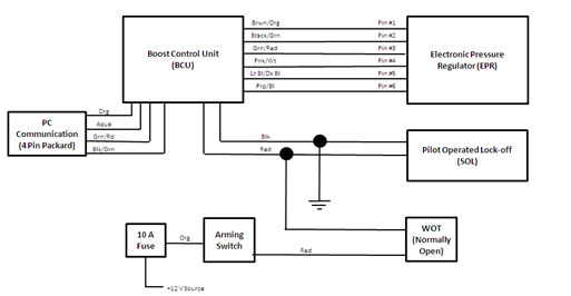
Remaining connections are installer specific. Schematics for Single Redundant and Double Redundant Triggering Schemes are shown below.
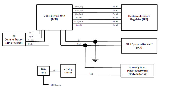
Single Redundant Wiring Diagram
The Single Redundant Triggering system uses a “high side” triggering scheme. The low side of the system is permanently grounded and a +12V one amp signal is used to trigger the system on when the system is armed and WOT has been reached.
WOT confirmation is normally accomplished via a normally open mechanical contact switch that is closed when WOT is reached, or by some other user configured switching mechanism, such as a piggy back circuit that monitors TPS voltage, as used on some fuel injected vehicles.
Wiring schematics and instructions for both mechanical contact switching and TPS monitoring are included to aid in your installation.
Single Redundant Wiring Schematic
Mechanical Triggering
Redundant Wiring Schematic
TPS Piggy Back Triggering
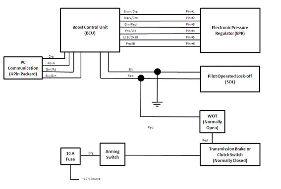
3.2.2 Double Redundant Wiring Diagram
The Double Redundant Triggering system uses a “high side” triggering scheme. The low side of the system is permanently grounded and a +12V one amp signal is used to trigger the system on when the system is armed , WOT has been reached and a normally closed mechanical contact switch is closed when either a clutch or trans brake is released. A wiring schematic and instructions are included to aid in your installation.
Double Redundant Wiring Schematic
Mechanical Contact Switch Triggering
With Supplemental Normally Closed Switch
-20 AN Main Supply Hose
Note: Assembling -20 SAE three piece hose ends can be challenging. At a minimum you will need a soft jaw vice and a 1-3/4in wrench. Compressed Air Supercharging has a special tool (P/N WR-XXX) that greatly simplifys this task. This tool is strongly recommended to minimize your grief and maximize the appearance of your finished hose.
- Layout hose (1H) along desired path between components (e.g. from Mechanical Regulator exit to Lock-off ). Care should be taken to protect hose from contact with suspension components, high temperatures (exhaust system components) and potential damage from road debris.
- Mark hose at desired length/cut location, remove hose from vehicle.
- Wrap hose at desired cut postion with electrical tape and cut to length with a hacksaw.
- Lubricate inside of hose with rubber lubricant such as Parker O-ring lube.
- Slide Hose End Collar (2H) on to hose and seat fully. Hose should come up and bottom against face of female threads inside Collar.
- Place Hose End Insert (3H) in bench vise soft jaws or in CAS WR-XXXX.
- Thread the Hose/Hose Collar assembly onto the Hose End Insert. After several turns the fitting will begin to “bite” into the hose and turning the Hose/Hose Collar will become difficult.
- Continue tightening the Hose/Hose Collar until the gap between the face of the Collar and the face of the Insert is less than .030-in.
- Remove hose assembly and repeat steps 4 through 8 on other end of hose.
Repeat steps 1) through 9) for any remaining hoses (Saftey Shut-off to EPR, or EPR to Ejector).
I. Introduction
ACT-156 is a pressure operated pneumatic linear actuator. It is designed to work with driving (operating) pressures of up to 125 psig on the backside of its diaphragm. It features a maximum stroke of approximately .27-inches. In its normal or relaxed mode, the shaft is retracted fully into the housing, extending when pressurized.
Providing reasonable care and cleanliness standards are maintained, the valve should provide many years of trouble free operation. Should the need for disassembly and inspection and/or maintenance be required, the following instructions are provided to guide you through the necessary steps.
II. Disassembly
- Screw two ¼-20 bolts into the retaining threads on the face of the Male Housing.
- Place a screwdriver between the two 14-20 bolts to act as a wrench.
- Place a 5/8 end wrench on the bung on the backside of the Female Housing. Loosen by turning in a CCW direction.
Note: The Male and Female Housing are Loctited together an may require a bit of elbow grease to loosen/separate.
- Separate Male Housing from Female Housing.
- Remove Piston Assembly, Spring and Diaphragm.
- Rotate (wiggle) Shaft and Ball Assembly in Piston to determine if the ball/socket joint is excessively loose (Ball should rotate freely but, you should not be able to feel any “slop” or clearance in the socket).
If disassembly of the Ball/Socket assembly is required, perform Steps 7 & 8. Otherwise proceed to Step 9.
- Remove “C” clip from piston with a pair of internal snap ring pliers.
- Remove Ball Socket and Shaft Assembly from Piston.
- Clean components with a light solvent such as mineral spirits if required. Dry with compressed air.
III. Inspection
- Examine Diaphragm and (if necessary) Ball for wear and/or damage.
- Replace damaged or worn components. Refer to ACT-156 assembly drawing for component part number information.
IV. Re-assembly
- Thread Shaft into Ball, hand tight, bottoming threads.
- Place Ball/Shaft assembly into Piston receiver pocket.
- Slide Socket over shaft, concave face towards piston and seat fully in Piston.
- Replace Internal Snap Ring in Piston receiver groove, seat fully.
- Place Diaphragm in Female Housing, ensuring that Diaphragm lip is fully seated in receiver groove and that Diaphragm is not puckered or wrinkled.
- Place Piston Assembly in Diaphragm, seat fully inside Diaphragm/Female Housing Assembly.
- Place several drops of Blue Loctite on Male Housing thread.
- Insert Spring in Piston receiver pocket.
- Hand tighten Male Housing in Female Housing.
- Torque housings together to 50-in lb.
Note: Do not over-torque Male Housing – Female Housing joint. Diaphragm distortion and ultimately failure will occur.I. Introduction
EJ-350 is a combination axial flow ejector, ambient air stream isolation (mechanical) valve assembly and over-boost protection device. During normal vehicle operation the unit remains fully passive with the ejector dormant, mechanical butterfly valve open and over-boost poppet valve shut.
When a properly configured CAS system is activated the butterfly valve shuts and the ejector discharges high pressure air into the intake tract of the vehicles engine. High ejector nozzle exit pressures and massflow rates result in significant axial thrust being generated by the ejector. The ejector needs to be securely mounted to reduce the likelihood of an intake hose coupling becoming dislodged and/or the ejector assembly becoming disconnected from the engine intake tract.
The ejector nozzle tip or “Motive Nozzle” tip plays an important role in tuning a CAS system to a specific engines’ airflow/power target. An inappropriately sized nozzle may still provide acceptable boost control but, for optimized response and boost level maintenance the proper tip should be employed. Refer to the CAS Bulletin titled “Ejector and Motive Nozzle Selection” for information on correctly selecting units for your application.
The “Pop-off” or relief setting of the over-boost valve is factory set as specified on the Ejectors’ labeling.
Providing reasonable care and cleanliness standards are maintained, the valve should provide many years of trouble free operation.
II. Mechanical Butterfly Assembly Inspection and Repair
The mechanical butterfly is spring loaded open and driven shut by the actuator ACT-156. Open and shut travel is limited by the adjusting screws located on the Actuator Arm Assembly. Anytime EJ-350 is disassembled, travel of the butterfly should be examined and adjustments to the stop screws performed as necessary prior to reassembly.
- Disconnect the Actuator from the Butterfly Assembly.
- Examine the Butterfly assembly for smooth operation. It should rotate smoothly from fully closed to fully open, without any hint of sticking at either limit of travel.
- If operation is smooth, continue with steps 4 through 8. If binding occurs during rotation, disassemble Butterfly Assembly, clean components with a light solvent such as mineral spirits and examine them for wear, damage or debris and replace components as necessary.
Note: The bushings contained in the Ejector Housing are graphite impregnated and do not require lubrication. If bushings are damaged they need to be removed with an arbor press and new units secured in place with adhesive. If you have an Ejector with damaged bushings, it is recommended that you return it to CAS for this service.
- Loosen the 10-24 set screw and lock nut that limit travel when the Butterfly is shut.
- Rotate the Butterfly fully shut. Slowly turn-in the 10-24 set screw until the Butterfly begins to lift off of its’ fully closed position (about ¼ to ½ turn open).
- Lock the set screw in place with the lock nut.
- Reattach the Actuator to the Butterfly Assembly. Looking into the Ejector with the Actuator fully relaxed, the butterfly should be parallel with the airstream. Loosen and adjust the 10-24 set screw that limits the fully open position as necessary.
- Lock the set screw in place with the lock nut.
III. Butterfly Actuator
Servicing of the Actuator is covered in the Service Bulletin titled “ACT-156 Service Bulletin”.
IV. Pop-off/Over-boost Protection Valve
The Over-boost Protection Valve is unlikely to need service unless its’ sealing O-ring has become damaged or dislodged or, a change in the pressure relief setting of the valve is desired.
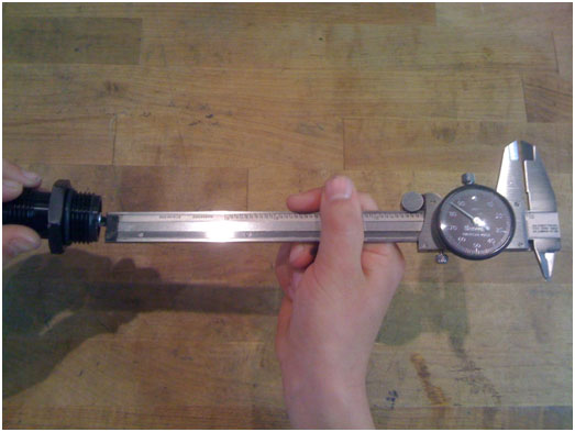
- Measure and note the position of the 9/16-in nut that holds the relief valve assembly in place. This can be done with the heel of a pair of dial calipers or by merely marking one face of the nut, noting its orientation then counting the number of turns required to remove the nut fully from its’ stud.
Note: If you desire to re-set the pressure at which an Over-boost valve operates at, each ½ turn of the 9/16-in nut equates to approximately XX psi.
- Clean components with a light solvent such as mineral spirits and examine them for wear, damage or debris and replace components as necessary.
- Reinstall Over-boost Protection Valve components.
- Re-tighten 9/16-in nut to original position to retain original pressure relief setting or, adjust to desired position.
I. Introduction
EPR-1260 is a electro-mechanically operated butterfly valve with integral position sensing. It is capable of traveling fully closed to fully open in 90 ms when operating at 12 V. The internals of the actuator are non-serviceable. External ancillary pieces such as SAE hose adaptors and seals can be replaced if damaged.
EPR-1260 is intended to operate with nominal supply pressures of 80 – 110 psig. Should the need arise to replace damaged external components, the accompanying exploded view is provided for sourcing replacements.
If you believe that your EPR-1260 has been damaged internally but, are unsure, it can be returned to the CAS Customer Service Department for evaluation.
Providing reasonable care and cleanliness standards are maintained, the valve should provide many years of trouble free operation.
II. Disassembly
- Unscrew and remove the four ¼-20 Cap Screws that hold the SAE Hose Adaptors to the Actuator Housing. The Adaptor that the Cap Screws thread into should separate from the Actuator Housing when the screws are removed.
- Slide the second Actuator Housing off of the snout of the Actuator Housing.
- Clean components with a light solvent such as mineral spirits if required. Dry with compressed air.
Note: It is not recommended that you remove the black plastic cover from the actuator housing. If you do, extreme caution must be taken to ensure that you do not damage the contact brushes on the Actuators’ main shaft.
III. Inspection
- Examine O-Rings, Throttle blade and bore for debris or damage. Butterfly should be closed when Actuator is de-energized.
- Rotate the Butterfly fully open with your fingers (it should be difficult to rotate as the Actuator employs a rather strong return spring).
- Release the Butterfly. It should slam shut in approximately .1 second
- Replace damaged or worn components. Refer to the accompanying exploded view for part number information.
IV. Re-assembly
- Install new O-rings in Adaptor Housings..
- Slide the Adaptor with the internal O-Ring (EPR-1574-3-R) onto the snout of the Actuator.
- Attach second Adaptor to Actuator/First Adaptor using ¼-in Cap Screws.
- Torque Cap Screws to 80in lb.
I. Introduction
SOL-1440 is a two stage electro-mechanical pilot operated solenoid valve. The first or pilot stage is direct acting, controlled by energizing or de-energizing the pilots’ 12V coil. Opening the pilot stage evacuates the reference cavity on the backside of the second stage or main diaphragm. This then creates a pressure imbalance on the diaphragm causing the second stage to open and allowing air to flow through the valves’ main passage way. De-energizing the pilot allows the second stage diaphragm reference cavity to equilibrate pressure across the diaphragm, allowing the diaphragm return spring to shut the valves’ main passage, stopping flow.
Providing reasonable care and cleanliness standards are maintained, the valve should provide many years of trouble free operation. Should the need for disassembly and inspection and/or maintenance be required, the following instructions are provided to guide you through the necessary steps.
II. Disassembly
- Remove the six 5/16 Allen Head Cap Screws that hold the Solenoid Cap the Solenoid Body using a ¼-in Allen wrench.
- Separate Solenoid Cap from Solenoid Body.
- Remove Diaphragm Return Spring and Diaphragm/Diaphragm Seal assembly.
- Remove Nut that retains Solenoid Coil to Solenoid Cap using CAS wrench P/N WR-SOL-1440-1.
- Remove Solenoid Coil Assembly from Solenoid Cap.
- Loosen and remove Solenoid Tower from Solenoid Cap using CAS wrench P/N WR-SOL-1440-1. Refer to Figure 1.
- Clean all components with a mild solvent such as mineral spirits. Dry with compressed air.
Note: Do not attempt to remove Solenoid Tower by grabbing the Towers’ shank with pliers. This will damage the tower irreparably.
Figure 1
III. Inspection
- Examine Solenoid Plunger face for damage or debris. The face of the Plunger Seal will likely have a small indentation where the Seal rests against the Pilot Seat, this is normal. Refer to Figure 2.
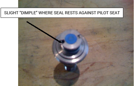
Figure 2
- Examine Diaphragm for tears, cuts, debris or other damage.
- Diaphragm Guide should easily slide into and out of the Receiver Bushing in the Solenoid Cap. Examine fitment for proper operation
- Replace damaged or worn components.
IV. Re-assembly
- Place Pilot Plunger Tower O-Ring in Solenoid Cap receiver.
- Place Pilot Plunger Return Spring on Pilot Plunger and insert in Solenoid Tower.
- Thread Solenoid Tower into Solenoid Cap. Secure using WR-SOL-1440-1.
- Install Solenoid Coil Assembly on Solenoid Tower/Solenoid Cap assembly.
- Secure Solenoid Coil with Nut.
- Insert Diaphragm Assembly in Solenoid Body.
Note: Make sure that molded O-rings on Diaphragm align with receiver grooves in Solenoid Body. Misalignment will result in an inoperable component.
- Place Diaphragm Return Spring on Diaphragm Guide.
- Align Solenoid Cap with Solenoid Body and Diaphragm Guide, Slide into place.
- Install six 5/16-in Cap Screws and Secure Solenoid Cap to Solenoid Body.
I. Introduction
REG-625 is a single stage balanced piston mechanical regulator. It is designed to maintain near constant outlet pressure of approximately 100 psig, for inlet pressure ranges from 3300 to 200 psig. Outlet pressure is preset at CAS via preload on the regulators’ two Diaphragm Springs. Diaphragm reference pressure is externally source to improve droop performance. Downstream components are protected from over-pressurization by the external Pressure Relief Device (PRD) which must be operational at all times.
During End of Line testing the internal leakage (inlet to outlet) of each regulator is checked at CAS to verify a “bubble tight” seal of less than .5 cc/minute. This is accomplished via tightly controlled tolerances and extremely fine surface finishes on the regulator plunger assembly and seat assembly.
REG-625 will provide consistent leak free performance assuming reasonable care and cleanliness standards are maintained. If the regulator seat becomes contaminated with dirt or debris, internal leakage can increase greatly. If this occurs, outlet pressure will climb above its set value until the Pressure Relief Device (PRD) vents, lowering outlet pressure back to acceptable levels.
Should the need for disassembly and inspection and/or maintenance be required, the following instructions are provided to guide you through the necessary steps.
Note: Cycling of the PRD can occur as the result of downstream leakage caused by hoses and/or fittings that are not tightly sealed. This will occur when the system is pressurized but, not flowing. Root cause is that downstream leakage causes outlet pressure to drop significantly below prescribed levels, causing the plunger assembly to cycle open and closed momentarily. This can then produce slight over-pressurization of the outlet and hence PRD venting.
Note: It is unlikely that operational issues will occur in the upper part of the Regulator (within the Spring Tower or Spring Cap). Any problems you are likely to experience will be related to contamination of the Regulator Cartridge Assembly. Servicing of the Regulator Cartridge REG-625-7-S can be accomplished without removal of the Spring Tower or Spring Cap. It is suggested that these components be left installed on the Regulator Body unless you believe that a problem has occurred directly with their operation.
Warning! The Spring Cap provides pre-load on the Inner and Outer Diaphragm Springs. Installed load is 550 lbs. Do not attempt to remove the Spring Tower or Spring Cap without proper tools such as an arbor press and guides for maintaining component position. Lack of proper tools and procedure can result in the catastrophic release of components, causing injury or death.
II. Disassembly-Cartridge
- Remove the Cartridge from the Regulator Body by loosening with a 1-3/4-in wrench.
- Loosen the Cartridge Cap from the Cartridge by holding the base with a 1-3/4-in wrench and turning the Cap CCW with a 1-1/8-in wrench.
- Once the Cap is loose, apply pressure to the tip of the Plunger Tower and finish unscrewing by hand.
Note: The Cartridge Cap is preloaded via the Plunger Spring and will launch the cap and Plunger Assembly if not properly restrained during disassembly.
- Remove Plunger Assembly and Plunger Spring.
- Remove and discard O-rings and Backup rings from Plunger Assembly and from Cartridge.
- Clean Cartridge, Cartridge Cap and Plunger Spring with Solvent such as Brakeleen. Dry with compressed air.
III. Inspection-Cartridge
- Clean Plunger Base and Plunger Tower with Mineral Spirits or similar non-aggressive solvent. Dry with compressed air.
- Examine Plunger Seat and Cartridge Cap sealing surface for contamination and damage. If undamaged, proceed to Re-assembly Instructions Step 5. If Cartridge Cap sealing surface is damaged it must be replaced. If Seat is damaged proceed to Re-assembly Instructions Step 1
IV. Re-assembly-Cartridge
- Unscrew Plunger Tower from Plunger Base using a ¼-in and 11/16-in wrench.
- Remove damaged Seat and discard.
- Install new Seat in Plunger Base.
- Install and tighten Plunger Tower in Plunger Base.
- Coat new Plunger O-rings and Backup rings with Parker Super O-Lube. Do not use other lubricants.
- Install new O-ring and Back-up rings as per Figure 1.
REG-625-8-S (Plunger Assembly) O-Ring Orientation
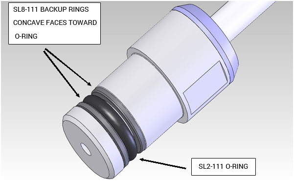
Figure 1
- Coat new Cartridge O-rings with Parker Super O-Lube. Do not use other lubricants.
- Install new O-ring and Back-up rings as per Figures 2 and 3.
IV. Re-assembly-Cartridge
REG-625-7-S (Cartridge Assembly) O-Ring Orientation
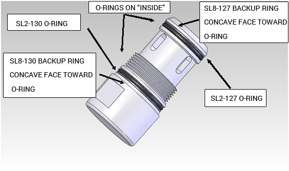
Figure 2
REG-625-7-S (Cartridge Assembly) O-Ring Orientation
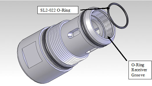
Figure 3
- Install Plunger Spring in Cartridge.
- Place Plunger Assembly in Cartridge.
- Slip Cartridge Cap over top of Plunger Tower stem.
- Carefully push (wiggle it as you apply pressure) Plunger Tower into Cartridge bore
Note: Improper installation can result in O-ring damage causing internal leakage and poor Regulator performance.
- Thread Cartridge Cap into Cartridge Housing. Secure using 1-3/4-in and 1-1/8-in wrenches.
Note: It is easy for the Cartridge to Cartridge Housing O-ring to get disturbed during this Step make sure that it is properly seated in its receiver groove in the Cartridge before securing the Cap. Improper installation can result in O-ring damage causing internal leakage and poor Regulator performance.
- Coat threads of Stem assembly with Krytox or similar Oxygen compatible lubricant.
- Reinstall Cartridge in Regulator Body using 1-3/4-in wrench.
V. Disassembly-Upper
Warning! The Spring Cap provides pre-load on the Inner and Outer Diaphragm Springs. Installed load is 550 lbs. Do not attempt to remove the Spring Tower or Spring Cap without proper tools such as an arbor press and guides for maintaining component position. Lack of proper tools and procedure can result in the catastrophic release of components, causing injury or death.
- Remove two oppositely located (180 degrees apart) 10-24-in cap screws that retain the Spring Tower Cap to the Spring Tower.
- Replace screws with 6-in long pieces of 10-24 threaded rod.
- Place Regulator in an arbor press.
Note: Press must have at least 4-in of upward travel from top of Spring Tower Cap to allow spring pressure to be fully released.
- Lightly load top of Regulator with press.
- Remove remaining 10-24 Cap Screws.
- Slowly remove load from top of Regulator.
- Remove Spring Tower Cap and Springs.
- Remove 5/16-in Cap Screws that hold Spring Tower to Regulator Body.
- Remove Spring Tower, Diaphragm and Diaphragm Backing Plates.
VI. Inspection-Upper
- Clean Diaphragm, Diaphragm Backing Plates, Spring Tower and Regulator using mineral spirits or a similar non-aggressive solvent.
- Inspect Diaphragm, Diaphragm Backing Plates and Diaphragm Sleeves in Spring Tower and Regulator Body for damage. Replace components as necessary.
VII. Re-assembly-Upper
- Place lower Diaphragm Backing Plate in Regulator Body.
- Place Diaphragm on Regulator Body.
- Place upper Diaphragm Backing Plate on top of Diaphragm.
- Place Spring Tower on top of Diaphragm. Radially located Diaphragm, upper Diaphragm Backing Plate and Spring Tower.
- Secure Spring Tower to Regulator Body using 5/16-in Cap Screws.
- Insert inner and outer pre-load springs in Spring Tower
- Radially Locate Spring Tower Cap on Spring Tower using 10-24 guide studs.
- Compress Springs using arbor press until Spring Cap is fully seated on Spring Tower.
- Secure Cap with six 10-24 Cap Screws.
- Remove guide studs.
- Install remaining two 10-24 Cap Screws.
I. Introduction
BV-625 is a two stage mechanical gate valve. Basic operation of the device involves turning the handle 1½ turns CCW to open the internal pilot valve. Doing so allows pressure in the system downstream of the valve to equalize with the pressure inside the CAS cylinder within several seconds. The valve handle can then easily be turned another 5 turns CCW to open the main section for maximum flow capability/minimum pressure drop. Closing the valve can easily be accomplished by turning the valve handle CW approximately 6 ½ turns.
Providing reasonable care and cleanliness standards are maintained, the valve should provide many years of trouble free operation. Should the need for disassembly and inspection and/or maintenance be required, the following instructions are provided to guide you through the necessary steps. Refer to Figure 1 and Table I for a complete listing of Bottle Valve components.
II. Disassembly
- Remove the Bottle Nut using a 1¼-in wrench.
- Remove the Nut Cover using a small screwdriver or pick.
- Remove the ¼-20 Nut that secures the Handle to the Valve. Remove Handle.
- Remove the Bonnet Assembly using CAS tool P/N WR-BV625-1. The Plunger Shaft will likely come out with Bonnet. If so, remove the Plunger Shaft from the Bonnet and insert it back into the square socket of the Stem Assembly.
- Remove the Stem Assembly by turning CCW with the Plunger Shaft.
III. Inspection
- Examine internal components for signs of damage or debris.
- Clean components using a mild solvent and dry with compressed air.
- Replace damaged or worn components.
IV. Re-assembly
- Coat threads of Stem assembly with Krytox or similar Oxygen compatible lubricant.
- Lubricate O-rings with Parker Super O-Lube.
- Thread Stem assembly into Valve Body using Plunger shaft.
- Re-assembly Cont’d
- Coat threads of Stem assembly with Krytox or similar Oxygen compatible lubricant.
- Lubricate O-rings with Parker Super O-Lube.
- Thread Stem assembly into Valve Body using Plunger shaft.
- If new O-rings and Seals were purchased, install Plunger Shaft Back-up Ring and O-ring in Bonnet as per Figure 1.
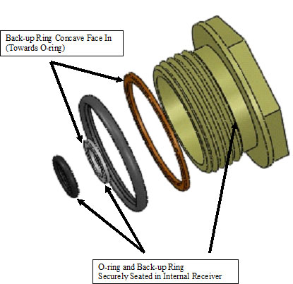
Figure 1
- Install O-ring and Packing seal on Bonnet.
- Thread Bonnet into Valve Body and secure with CAS tool P/N WR-BV625-1.
- Install Handle using ¼-20 Nut and Washer.
- Install Nut Cover.
- Install O-rings in outlet face of Valve Body and outlet face of Bottle Nut.
- Thread Bottle Nut on to Valve Body and secure.
I. Introduction
PRD-625 is a mechanical “pop-off” style pressure relief device, designed to work with CAS mechanical pressure regulators to prevent over-pressurization of downstream components in the event of excessive regulator seat leakage or pressure regulation failure. PRD-625 is factory set to relieve pressure once downstream pressure exceeds 130 psig.
Warning! A downstream PRD must always be used with all CAS systems. Failure to do so may result in catastrophic failure of downstream components causing injury or death.
During End of Line testing the internal leakage (inlet to outlet) of each PRD is checked at CAS to verify a “bubble tight” seal of less than .5 cc/minute. This is accomplished via tightly controlled tolerances and extremely fine surface finishes on the plunger assembly and seat.
PRD-625 will provide consistent leak free performance assuming reasonable care and cleanliness standards are maintained. If the PRD seat becomes contaminated with dirt or debris leakage can increase greatly. If this occurs, the PRD will vent downstream pressure to atmosphere, depleting the contents of your system.
Note: Cycling of the PRD can occur as the result of downstream leakage caused by hoses and/or fittings that are not tightly sealed. This will occur when the system is pressurized but, not flowing. Root cause is that downstream leakage causes outlet pressure to drop significantly below prescribed levels, causing the plunger assembly to cycle open and closed momentarily. This can then produce slight over-pressurization of the outlet and hence PRD venting.
Should the need for disassembly and inspection and/or maintenance be required, the following instructions are provided to guide you through the necessary steps.
II. Disassembly
Warning! When disassembling and re-assembling the PRD, 7/16-in nut must be relocated in the same position (depth wise) that it was removed from. Failure to do so will change the pressure setting at which the device vents. This can render the PRD inoperable. An inoperable PRD may result in catastrophic failure of downstream components causing injury or death.
- Remove the PRD from the Regulator Body by loosening with a 1-3/8-in wrench.
- Measure and record the distance from the end of the Plunger Stud to the face of the 7/16-in Nut using dial calipers. See Figure 1
- Insert a ½-in socket into the outlet of the PRD and acquire the PRD Cap. Hold securely.
- Loosen and remove the 7/16-in plunger nut.
Note: The Plunger Nut has approximately 50 lbs of spring pressure against it when fully seated. The Nut and Spring Retainer will be launched if not properly restrained during removal.
- Remove Spring Retainer, Spring and Stem from PRD Housing.
III. Inspection-Cartridge
- Clean all components with Mineral Spirits of similar non-aggressive solvent. Dry with compressed air.
- Examine Seat and PRD Housing sealing surface for contamination and damage. If undamaged, proceed to Re-assembly Instructions Step 5. If PRD Housing sealing surface is damaged it must be replaced. If Seat is damaged proceed to Re-assembly Instructions Step 1.
IV. Re-assembly-Cartridge
- Unscrew PRD Stem from PRD Cap using a 3/16-in and 1/2-in wrench.
- Remove damaged Seat and discard.
- Install new Seat in PRD Cap.
- Install and tighten Plunger Stem in Plunger Cap.
- Coat new area of Stem that rides in housing guide with Krytox or similar oxygen compatible lubricant.
- Insert Stem Assembly into PRD Houisng
- Insert Spring into PRD Housing.
- Place Spring Retainer on Spring, flat side out.
- Compress Spring/Retainer so that 7/16-in Nut can be started on Stem threads.
- Using ½-in socket and 7/16-in wrench return Nut to original axial position.